


| Measurement functions | Measurement range | Display range | Resolution | Accuracy |
|---|---|---|---|---|
| Fault loop impedance | ||||
| Fault loop ZL-PE, ZL-N, ZL-L | 0.13 Ω…1999.9 Ω acc. to IEC 61557 | 0.00 Ω…1999 Ω | from 0.001 Ω | ±(5% m.v. + 30 digits) |
| Fault loop ZL-PE in RCD mode | from 0.50 Ω…1999 Ω acc. to IEC 61557 | 0.00 Ω…1999 Ω | from 0.01 Ω | from ±(6% m.v. + 5 digits) |
| Measurements of RCD parameters | ||||
| RCD tripping test and measurement of tripping time tA measuring current 0.5 IΔn, 1 IΔn, 2 IΔn, 5 IΔn | ||||
| general and short-time delay RCD | 0 ms…300 ms | 0 ms…300 ms | 1 ms | from ±(2% m.v. + 2 digits) |
| selective RCD | 0 ms…500 ms | 0 ms…500 ms | 1 ms | from ±(2% m.v. + 2 digits) |
| Measurement of RCD tripping current IA measuring current 0 0.2 IΔn…2.0 IΔn | ||||
| for sinusoidal residual current (AC type) | 3.3 mA…1000 mA | 3.3 mA…1000 mA | from 0.1 mA | ±5% IΔn |
| for unidirectional residual current and unidirectional with the 6 mA DC bias (type A) | 3.5 mA…700 mA | 3.5 mA…700 mA | from 0.1 mA | ±10% IΔn |
| for direct residual current (type B) | 2.0 mA…1000 mA | 2.0 mA…1000 mA | from 0.1 mA | ±10% IΔn |
| Earth resistance | ||||
| 3- and 4-pole method | from 0.50 Ω…1.99 kΩ acc. to IEC 61557-5 | 0.00 Ω…1,99 kΩ | from 0.01 Ω | from ±(2% m.v. + 3 digits) |
| 3-pole + clamp method | 0.00 Ω…1.99 kΩ | 0.00 Ω…1.99 kΩ | from 0.01 Ω | from ±(2% m.v. + 4 digits) |
| 2-clamp method | 0.00 Ω…99.9 kΩ | 0.00 Ω…99.9 kΩ | from 0.01 Ω | from ±(10% m.v. + 4 digits) |
| Resistance-to-earth | 0.0 Ω m…99.9 kΩm | 0.0 Ωm…99.9 kΩm | from 0.1 Ωm | Depending on accuracy of RE measurement |
| Insulation resistance | ||||
| Measuring voltage 50 V | 50 kΩ…250 MΩ acc. to IEC 61557-2 | 0 kΩ…250 MΩ | from 1 kΩ | from ±(3% m.v. + 8 digits) |
| Measuring voltage 100 V | 100 kΩ…500 MΩ acc. to IEC 61557-2 | 0 kΩ…500 MΩ | from 1 kΩ | from ±(3% m.v. + 8 digits) |
| Measuring voltage 250 V | 250 kΩ…999 MΩ acc. to IEC 61557-2 | 0 kΩ…999 MΩ | from 1 kΩ | from ±(3% m.v. + 8 digits) |
| Measuring voltage 500 V | 500 kΩ…2.00 GΩ acc. to IEC 61557-2 | 0 kΩ…2.00 GΩ | from 1 kΩ | from ±(3% m.v. + 8 digits) |
| Measuring voltage 1000 V | 1000 kΩ…4.99 GΩ acc. to IEC 61557-2 | 0 kΩ…9.99 GΩ | from 1 kΩ | from ±(3% m.v. + 8 digits) |
| Resistance of protective conductors and equipotential bondings | ||||
| Measurement of resistance of protective conductors and equipotential bondings with ±200 mA current | 0.12 Ω…400 Ω acc. to IEC 61557-4 | 0.00 Ω…400 Ω | from 0.01 Ω | ±(2% m.v. + 3 digits) |
| Measurement of resistance with low current | 0.0 Ω…1999 Ω | 0.0 Ω…1999 Ω | from 0.1 Ω | ±(3% m.v. + 3 digits) |
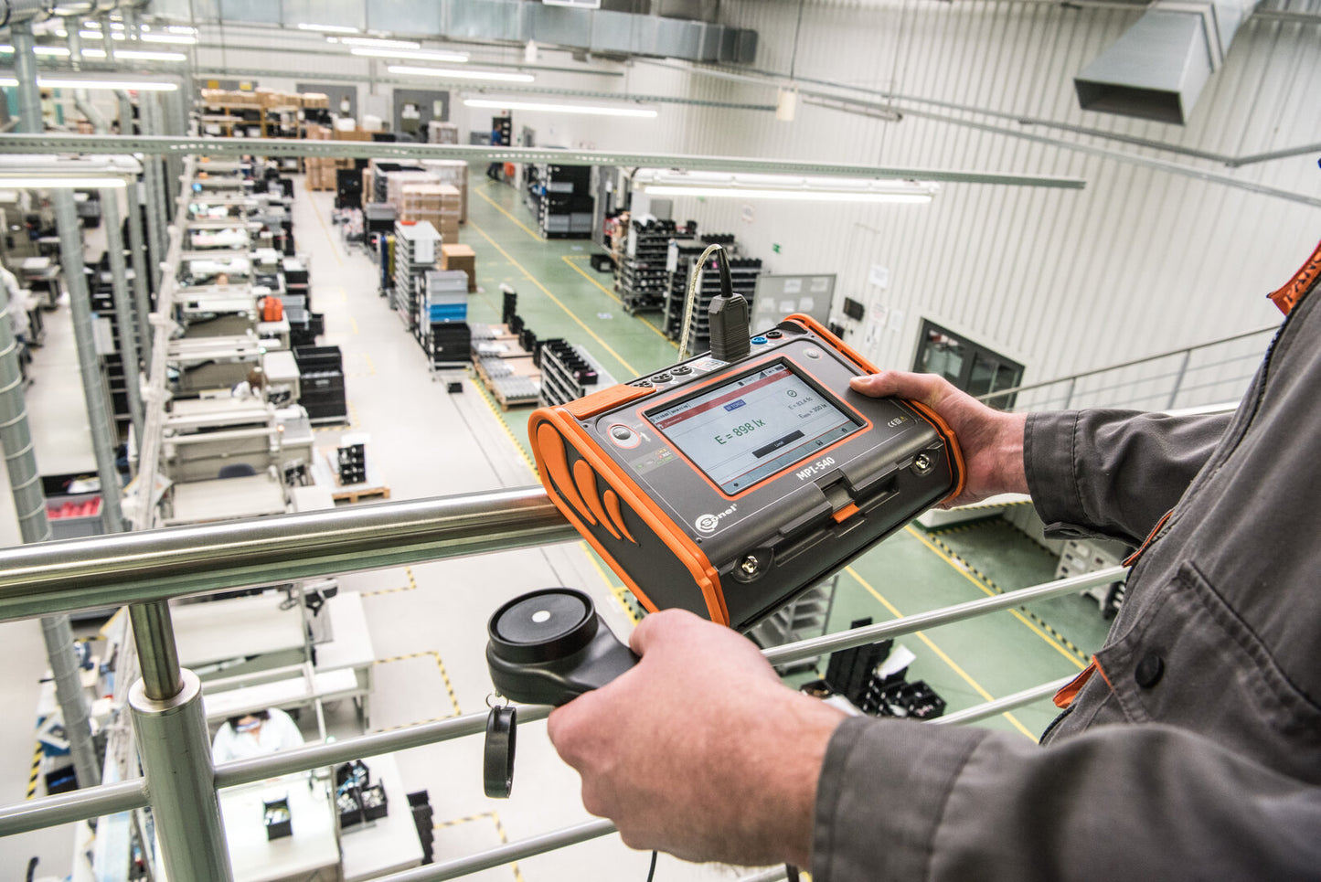
| Light intensity | ||||
| Measurement in luxes (lx) | 0 lx…399.9 klx | 0 lx…399.9 klx | from 0.001 lx | from ±(2% m.v. + 5 digits) |
| Measurement in feet-candles (fc) | 0 fc…39.99 kfc | 0 fc…39.99 kfc | from 0.001 fc | from ±(2% m.v. + 5 digits) |
| Phase sequence indication | in the same direction (correct), opposite direction (incorrect), UL-L voltage: 95 V…500 V (45 Hz…65 Hz) |
“m.v.” - measured value
Specifications – 3-phase power quality recorder
The device is designed to work with mains:
- with nominal frequency 50/60 Hz
- with nominal voltage: 64/110 V, 110/190 V, 115/200 V, 127/220 V, 220/380 V, 230/400 V, 240/415 V, 254/440 V, 290/500 V
- DC networks
Supported systems:
- single-phase
- split-phase with common N
- three-phase – WYE with and without N conductor
- three-phase – Delta
| Parameter | Measuring range | Max. resolution | Accuracy |
|---|---|---|---|
| Alternating voltage (TRMS) | 0.0…500 V | 0.01% Unom | ±0,5% Unom |
| Alternating current (TRMS) | depending on clamp* | 0.01% Inom | ±2% m.v. if m.v. ≥ 10% Inom, ±2% Inom if m.v. < 10% Inom , (error does not account for clamp error) |
| Frequency | 40.00…70.00 Hz | 0.01 Hz | ±0.05 Hz |
| Active, reactive, apparent and distortion power | depending on configuration (transducers, clamps) | 4 significant digits | depending on configuration (transducers, clamps) |
| Active, reactive and apparent energy | depending on configuration (transducers, clamps) | 4 significant digits | as power error |
| cosφ and power factor (PF) | 0.00…1.00 | 0.01 | ±0.03 |
| Harmonics | |||
| Voltage | as for alternating voltage True RMS | as for alternating voltage True RMS | ±5% m.v. if m.v. ≥ 3% Unom, ±0,15% Unom if m.v. < 3% Unom |
| Current | as for alternating current True RMS | as for alternating current True RMS | ±5% m.v. if m.v. ≥ 10% Unom, ±0,5% Unom if m.v. < 10% Unom |
| THD | |||
| Voltage | 0.0…100.0% (relative to RMS value) | 0.1% | ±5% |
| Current | 0.0…100.0% (relative to RMS value) | 0.1% | ±5% |
| Unbalance factor | 0.0…10.0% | 0.1% | ±0.15% (absolute error) |
*
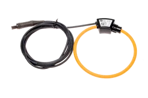
- F-1A, F-2A, F-3A clamp: 0…3000 A AC (10 000 Ap-p)
- C-4A clamp: 0…1000 A AC (3600 Ap-p)
- C-5A clamp: 0…1000 A AC/DC (3600 Ap-p)
- C-6A clamp: 0..10 A AC (36 Ap-p)
- C-7A clamp: 0…100 A AC (360 Ap-p)
AC currentmeasurment (True RMS) with clamp
| C-4A | C-5A | C-6A | C-7A | F-1A | F-2A | F-3A | |
|---|---|---|---|---|---|---|---|
| Rated current | 1000 A AC | 1000 A AC 1400 A DC |
10 A AC | 100 A AC | 3000 A AC | 3000 A AC | 3000 A AC |
| Frequency | 30 Hz…10 kHz | DC…5 kHz | 40 Hz…10 kHz | 40 Hz…1 kHz | 40 Hz…10 kHz | 40 Hz…10 kHz | 40 Hz…10 kHz |
| Max. diameter of measured conductor | 52 mm | 39 mm | 20 mm | 24 mm | 380 mm | 250 mm | 140 mm |
| Minimum accuracy | ≤0,5% | ≤1,5% | ≤1% | 0,5% | 1% | 1% | 1% |
| Battery power | - | √ | - | - | - | - | - |
| Lead length | 2.2 m | 2.2 m | 2.2 m | 3 m | 2.5 m | 2.5 m | 2.5 m |
| Measurement category | IV 300 V | IV 300 V | IV 300 V | III 300 V | IV 600 V | IV 600 V | IV 600 V |
| Ingress protection | IP40 | IP40 | IP40 | IP40 | IP67 | IP67 | IP67 |
Weight and dimensions
| Parameter | Value |
|---|---|
| Net weight (kg) | 2.3 |
| Package weight (kg) | 8.1 |
| Package width (cm) | 50 |
| Package height (cm) | 19 |
| Package length (cm) | 32 |
Accessories included with the meter